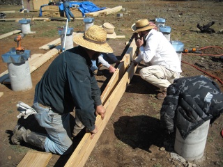
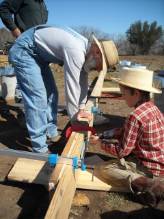
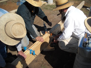
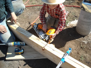
Our journal of what we pray is our sojourn of life along the narrow way, even the old paths, submitting to the Bible as a light unto both.

Category: house (Page 7 of 8)

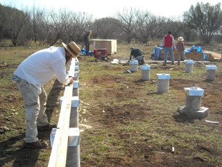
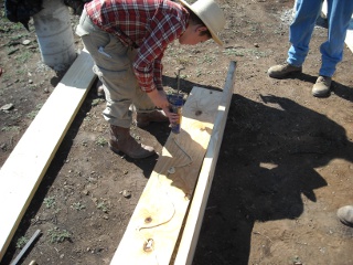
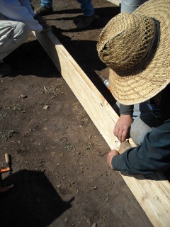
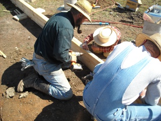
A House – Update XI – Porch Cross Beams

After the house pony walls were in place, it was time to start on the porch cross beams!

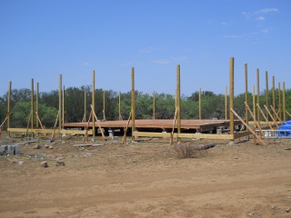
Since we did the porch posts some time ago, they had opportunity to start to torque and bend in the air. I had hoped to get to the cross beams sooner so this problem would be limited, and I never cut them off in hopes that most of the twisting would happen on the top parts that would be cut off; and now in retrospect, I probably should have done the porch posts and cross beams at the same time; but that wasn’t going to help now; and so, one of the biggest issues we had to overcome was the un-level, twisted posts.

At first, we used the truck and a ratchet strap to level the posts:

Porch Posts Leveled with Truck and Ratchet Strap

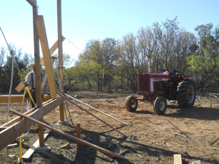
But then switched to using the tractor because it was more maneuverable into the tighter areas around the house:

Porch Posts Leveled with Tractor and Ratchet Strap

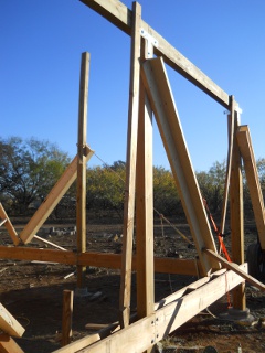
A few posts only required a single 2×6 brace to get them untwisted:

Porch Post Twisted Straight with One 2x6

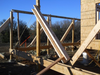
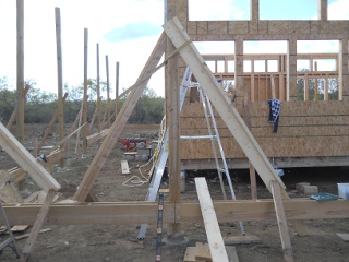
Others required two, in the shape of an “L”, and with some of these we did a brace on each side (also notice the 2×4 from the cross beams, which was used to twist it flat onto the top of the post):

Porch Post Twisted Straight with Two 2x6s in an L Shape with a Cross Beam Torquing 2x4

Quite a few required three 2x6s in the shape of a “U”, which gave us a lot of twisting counter-pressure:

Porch Post Twisted Straight with Three 2x6s in a U Shape

Here is a post leveled with the ratchet strap off of another post, and two “L” braces in place keeping it torqued straight (although, we could have probably done it with only one “U” brace instead):

Porch Post Leveled with Ratchet Strap, Twisted Straight, and Braced

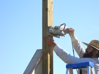
Once leveled and twisted in shape, the tops were cut off:

Cutting Off the Top of the Porch Post

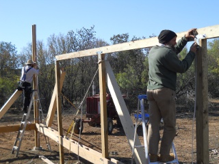
In similar fashion to leveling the foundation piers, we used the water level from one post to another, and we tried to use the same starting post each time so any errors introduced were not additive:

Using the Water Level to Get the Level from One Post to the Next

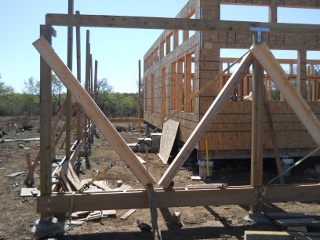
And here is a cross beam in place. The cross beams are treated 4x6s, like the porch posts:

Porch Cross Beam in Place

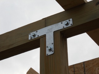
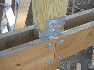
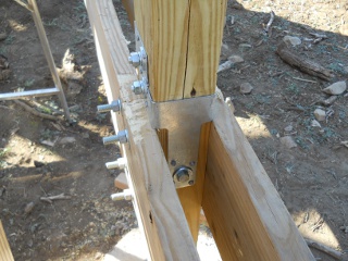
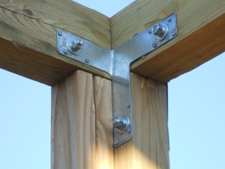
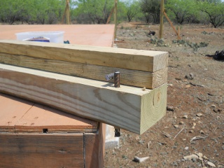
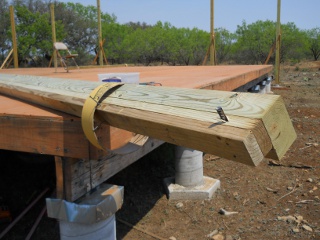
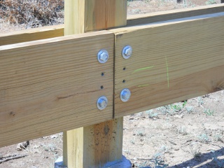
We used two T-straps, inside and outside, to join each post to each cross beam, used 3 1/4″ 16d galvanized “Common” nails to attach the T-straps (come to find out, there are 3 1/4″ 16d galvanized “Box” nails, which have a smaller diameter and aren’t as stout, even though they cost more at the place we got them), and used bolts to further secure them:

Porch Cross Beams Joined with T-Strap

So, as I mentioned, we were able to put quite a bit of twisting force on the posts to get them straight, which some of them really required. One of the biggest fears with that though was having the post come apart from too much twisting.

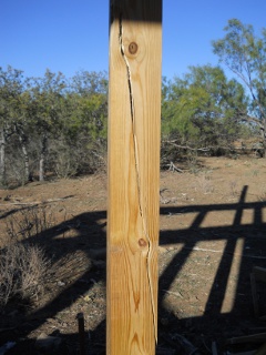
Well, with one badly torqued post, we got it almost straight. I looked at it, and looked at it, and said, “Just a little more, to get it just a little more straight.” And yep, that was it…snap! Bummer:

Porch Post Broken After Too Much Twisting

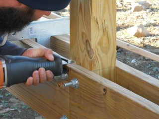
Well then, what to do. Mr. Gurau, who has been helping with the house building, had an idea. He first cut off the post at the porch floor joist support level:

Cutting Off Broken Porch Post
Broken Porch Post Cut Off

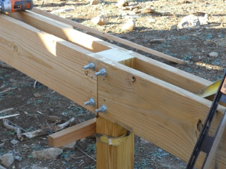
And here is how he installed the replacement post, using the T-straps:

New Porch Post Strapped in Place
Another View of New Porch Post Strapped in Place

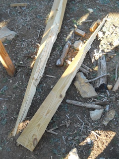
Here is what it looked like when it fell to the ground after being cut off. In thinking about it, the Lord might have been especially gracious in allowing the post to crack now, giving us opportunity to replace it now, rather than having to do it some time in the future, when the whole porch roof was up:

Broken Porch Post on the Ground in Pieces

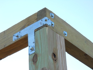
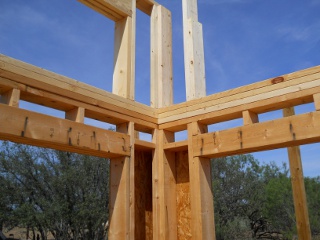
As Mr. Gurau progressed and got to the corners, here is how he handled them, using the T-straps:

Outside Corner of Porch Cross Beams with T-Strap
Inside Corner of Porch Cross Beams with T-Strap

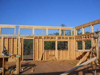
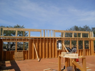
And here are the porch posts complete!

Completed Line of Porch Cross Beams
Another Completed Line of Porch Cross Beams

We’re grateful again to God for granting us provisions for the house, and for the help in Mr. Gurau He has allowed, and for Mr. Gurau’s continued safety while he works, for which we continue to pray.

— David
A House – Update X – Giddy-Up, Pony Walls

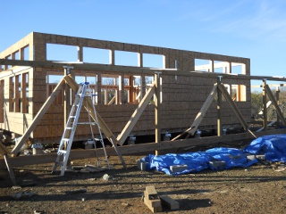
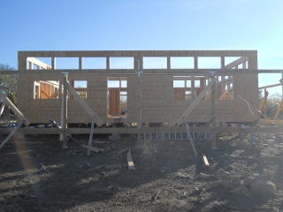
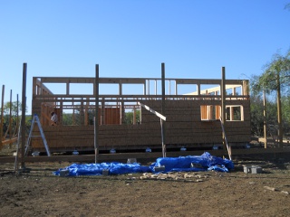
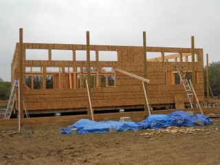
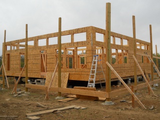
Originally in the house design, I had intended to put dormers in the roof below the interior ceiling. This would allow light and air circulation into the living space of the house through the roof. However, upon reconsideration, given the planned roof design, and after receiving advice, I decided to put up “pony” walls — short walls that in our case would contain windows. The porch roof would come up to the main walls below the pony wall windows, and the house roof would be above them; this would allow for even greater light and ventilation, and would be easier to implement.

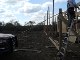
And so, after the house exterior walls were complete, the man in the group who’s been helping me with the house started in on them.

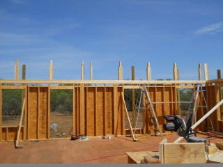
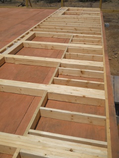
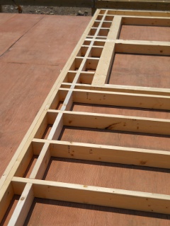
Here are some of the initial framing pieces in place:

House Pony Walls Framing

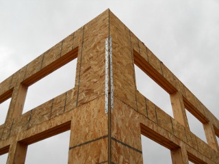
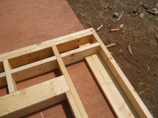
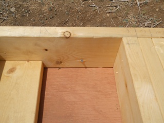
And here’s a picture of a corner:

House Pony Walls Corner

The following are a few pictures of the pony walls with the window headers in place. I decided to use 2×10 headers with 1/2″ OSB in between to hopefully make sure the weight of the roof would never sag the windows (I had originally thought perhaps to use 2×8, but in our local store where I bought the wood, the 2x10s were not much more expensive plus added that extra 2 inches of strength):

House Pony Walls from Inside with Headers
House Pony Walls from Outside with Headers

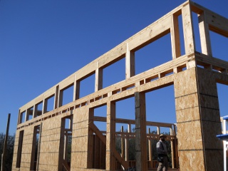
And here they are completed…

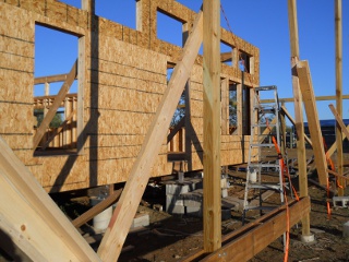
House Pony Walls Complete

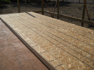
…and then with the OSB siding in place. These OSB pieces were nailed into the main wall as well, which tied the two walls together:

House Pony Walls Complete with OSB

And finally, some tie straps were added to further secure the two walls to each other:

House Phony Walls Strap Ties

The man who has recently moved down with his family and is helping me has worked construction before, so we’re thankful to the Lord for his advice and assistance. And we thank God also for continued provisions and progress on the house. We pray one day it’ll be a welcoming place for meeting in fellowship with the brethren.

— David
A House – Update IX – Exterior Walls

After the house’s porch posts, it was time to put up the exterior walls. After all of the other much slower-moving parts of the house, like the concrete piers, etc., it’s nice to be at a point where things move a little quicker.

Here is the first wall framed. The window headers, which sit on the cripple studs to which the sides of the windows are attached, we made by “sandwiching” 2 pieces of 1/2″ plywood between 3 2x6s; and the window sills sit on smaller cripples, forming the rest of the window frame. The doors, not a part of this wall, we did similarly. We will double the top plates, using the upper top plate to overlap and tie the corners together:

House Outer Wall Frame

And here is the wall with the fire blocks in place. The distance that the OSB siding would be lowered down the wall to attach to the floor joists header determined where these went:

House Outer Wall Frame with Fire Blocks

This is how we did the corner, to be able to attach another wall to it and to allow for internal siding to have something to which to be attached:

House Outer Wall Frame Corner

We set a chalk line 5 1/2″ inches back from the edge of the floor, lined up the wall frame to it, and tacked the bottom plate to the floor every 4-6 feet to keep the wall from sliding when lifted into place:

House Outer Wall Frame Base Plate Tacked to Floor

We attached the OSB siding while the frame was on the ground, because placing the 4×8 foot panels when the wall is vertical is much more difficult. I chose OSB because it was cheaper, and I figured would work just about as well, although there are discussions on the Internet that using plywood is better:

House Outer Wall Frame with OSB Siding

And then, we cut out the windows using a router, which made it VERY easy. In the end, even with the siding on, especially with the windows and doors cut out, it wasn’t really too heavy to lift into place:

House Outer Wall Frame with Windows Routed Out

Here’s the video of the raising of the walls. We thank the Lord for granting us the brethren to help and be a part of this as part of a community:

Raising of the House Walls

With the diagonal braces on the outside holding up the walls, we had to come back in later and add a few pieces of the OSB siding. Once placed, the windows had to be then cut out; and here is a video of me doing that. The router is REALLY nice for this process. Judging from the video, this is why we try to do as many of these while the wall is on the ground 🙂 :

Routing Out Some House Wall Window Frames

As always, we are grateful to the Lord for granting the provisions to be building the house, the strength to do so, we pray guidance and safety in doing so, and for the brethren to help in its construction; and we pray one day the house will be used as a place of worship and fellowship of God’s people.

— David
A House – Update VIII – Porch Posts

After the floor of the house was completed, it was time to get the porch posts into the ground, because I didn’t want to put up the wall frames and then have to wait all of the time to do the porch posts with the wall frames sitting out that much longer in the elements.

I decided to make the porch 10 feet, because I wanted to have enough room to have the community sit outside all together; and I wanted to have it go all the way around the house, so that we could sit under a porch and be out of the sun, or in the sun, or in a breeze, regardless of time of day or weather conditions.

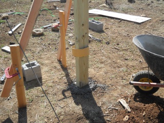
I also decided to go with a single post all the way into the ground vs. only doing a platform and attaching the roof posts after — it just seemed the single porch post would be more sturdy. Further, I decided to use 4×6 inch treated lumber for the posts. The biggest issue with these are that these types of treated posts can sometimes start to torque and bend in the sun; but I figured that if I could get to them quickly enough, it wouldn’t cause too much trouble.

And so the process began…

I set up the stringer for a line of posts, and here set it up for the corner:

Line Strings Set Up for Corner Porch Posts

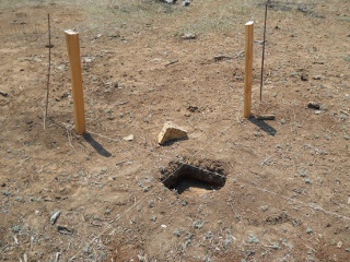
And here’s the hole dug for the corner with the brace supports pounded into the ground. At the bottom of each hole, I beveled out the bottom so the dirt above the bevel would hold the concrete more securely in the ground:

Porch Post Hole Dug and Brace Supports Set

For the corners, I decided to attach two 2×4’s on one long side of the 4×6, which made the post “L”-shaped. I also drilled holes and pounded in rebar so as to hold the post more firmly in the concrete:

Corner Porch Post with Rebar

To build the concrete up around the post slightly, so as to keep the soil from touching the wood, and to make it a little nicer looking, I used 8 inch (12 inch for the corners) concrete tubes cut at 4 inches high, and would slide it up the post, propping it up with screws, before standing up the post in the hole:

Porch Post with Concrete Footer Tube Pre-set in Place

Here is a post set in the ground before final floating of the concrete and setting the concrete tube footer:

Porch Post in Set in Concrete with Braces and Before Tube Footer Set

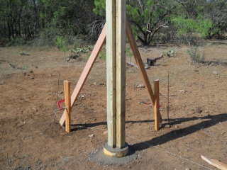
And here is a post completed, including the tube footer:

Porch Post in Set in Concrete with Braces and Tube Footer Set

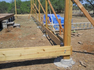
With each side of the house being 40 feet, thus making a porch side 60 feet, I decided to place each post around 10 feet apart (it actually ended up being 9 feet, 10 inches, to allow for some overhang of the porch joists), and then figured to use double 2×10 inch treated boards for the joist supports. I also put two spacers between the two boards, about 1/3 of the way in from each post. To level the boards from post to post, we used the same water level we used in leveling the concrete piers of the main house structure; and we leveled each post based on a single post so that any error introduced into the leveling would not be cumulative. Also, before attaching the joist supports, I’d have to sometimes use ratchet straps to re-level vertically the two posts I was working with, because they would sometimes over time start to get a little off-level:

Porch Joist Braces in Place

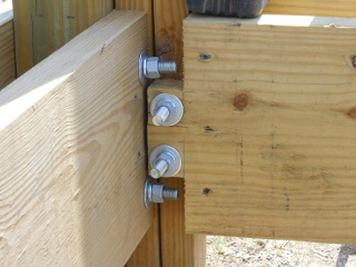
Here’s an inside look of how I joined the corners. I used 1/2 inch hex bolts and screws to hold them up. Also, I had to add another piece of 2×4 between the boards attached to the two vertical 2x4s that were part of the overall post to be able to add a little more support for the boards (I probably should have had those part of the main post structure):

Porch Post and Joist Brace Join at Corner

And here is a middle post join:

Porch Post and Joist Brace Join

And here they are all in place!

Porch Posts Set All Around the House

As I had feared, some of the posts are starting to twist and bend; but hopefully we’ll be able to straighten them enough to where that won’t cause long-term issues.

We’re grateful again to God for allowing us the resources and strength to work on the house; and we look forward to continued progress on it, as He might will.

— David
A House – Update VII – Floored

With the foundation beams up, it was time to start on the floor.

Floor Joists

Given the approximately 8 foot spans, I chose to go with 2x8s for the floor joists, which I planned to overlap on each beam, spaced 16 inches on center. (I had originally thought I would need the entire piers under the floor; but in looking back, given there is planned to be a porch, I probably would have brought the ends of the floor to sit right on the beams.)

I started with the ends, which I decided to double because they were going to support the gabled walls; and I staggered them, similarly to the built-up beams. Also, since I would be overlapping the joists as they crossed the beams, this would offset the joists 1 1/2 inches off from the 16 inch on center layout, which would cause problems with being able to lay the subfloor down evenly centered on joists. However, having these end joists doubled would allow for shifting the subfloor boards to once again end up sitting evenly centered on the joists. The final subfloor board in a course would end up 1 1/2 inches off the end, which I would cut off and put back on the other side, which had been shifted 1 1/2 inches away from the end:

House Floor Outer Joists

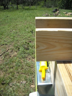
After putting them up on both sides, I ran a header string from each built-up joist…

House Floor Outer Joists with Header String

…which would be used to line up the internal joists with each other:

Floor Joist Lined Up with Header String

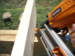
Once a joist was in place, I toe-nailed it to the beam….

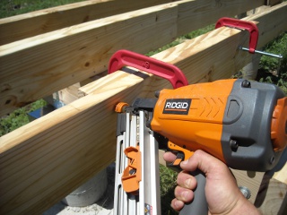
Toe-Nailing Floor Joist with Nail Gun

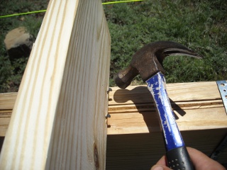
And finished them by hammering them in further. Being right-handed, it was fun to learn and practice hammering with my left hand:

Hammering In Floor Joist Toe-Nails

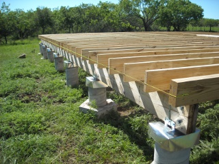
And here is one side of the joists all set in a line:

Joists Lined Up with Header String

This is the overlapping of the joists. With any warped boards, I would sometimes have to clamp them together to be able to nail them together properly:

Nailing Together Overlapping Joists

I added spacers between the joists to straighten them and give the overall floor more stability. Also, I put them on the beams, again, for more stability:

Spacers Between Floor Joists

After getting the joists in place, I added the header boards:

Floor Joists Header

Because we are planning on having an inner wall down the middle of the house, and the middle of the house is in between two beams, on every other joist on the middle row of joists, I doubled the joists to give extra support to that wall. I doubled joists for another inner wall that’s to run parallel with the joists; and in this picture, I added several doubled joists in a row, which is where we are planning to put our wood burning stove:

Double Floor Joists for Extra Support

To help against wind lift and to better secure the joists to the foundation, I attached each joist where it crossed each beam with hurricane clips:

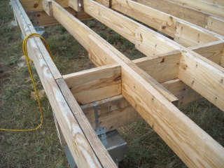
Hurricane Clips Connecting Floor Joist to Foundation Beam

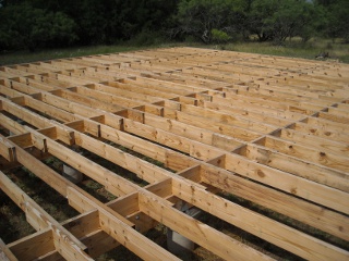
And here are the joists completed…

Middle of Completed Floor Joists

…facing South…

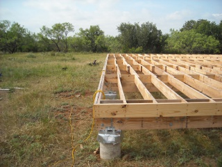
Full Picture of Completed Floor Joists Facing South

…and facing West:

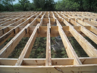
Full Picture of Completed Floor Joists Facing West

Subfloor

For this, I chose 3/4 inch tongue and groove plywood; the tongues and grooves fit together to make the places where the boards span floor joists much more stable. I also heard it was good to glue them to the joists and use screws, so I used external Liquid Nails for the glue and 3 inch deck screws to secure them, placing screws 8 inches apart on the board edges and 1 foot apart at the internal points on the joists. The board would be fastened down short end to short end across the whole platform, making a “course”; and each course would be staggered from the previous one by half the board.

When I first started, I didn’t really think through which long end type I should place against the first outside corner, the tongue side or groove side of the board. Well, I chose groove side, because it didn’t seem right to use the tongues side. Well, this stroke of genius started me on a path where with each subsequent course I was trying to fit the groove into the tongue. Needless to say, it was quite difficult, although I finally did get into a pattern where I’d loosen the screws next to the tongue of the previous course and use the mini-sledge hammer to knock them up and loose from the glue so they would flex better when I was trying to slide the groove onto the tongue. I also learned to clean out the groove and clean the tongue so nothing was in the way of them coupling. All of this worked ok until I learned from those much smarter than me that you could hit a board against the opposite site to force the tongue and groove together. I thought I had tried it before; but when I tried it again, it worked great. Of course, by then I only had about a course and a half left. 🙂

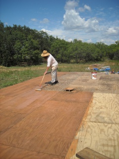
At any rate, given how long it took to get the floor on, I figured it was going to be a while before the house is dried in, so we painted the subfloor with water sealer, tinted cedar color (just to make it darker as a personal preference). Notice the stagger pattern of the boards from course to course:

Painting Subfloor with Water Sealer

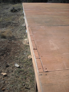
Here is a course where the boards were shifted 1 1/2 inches to accommodate the overlapping of the floor joists, and I cut off the other overhanging end of the last board of this course and brought it over to this end to fill in the gap:

Subfloor Offset Fill Piece

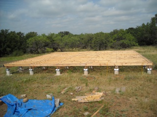
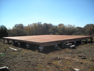
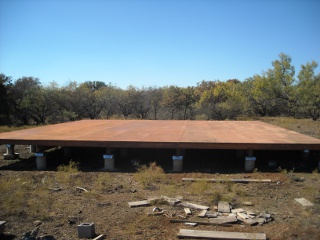
And here is the platform finished. Thanks to Sue for all of her helping me get the boards in place, and for painting the rest of the floor and repainting my terrible painting job!

Completed Subfloor Facing Southwest
Completed Subfloor Facing West

Even though it took several months, it’s finally done; and we thank the Lord for the continued progress on the house.

— David
A House – Update VI – Beams Be Up, Scotty

Once the concrete piers for the house were completed, and the homemade termite shields in place, it was time to put on the beams. I decided to use built-up beams (which is basically constructing together beams out of thinner wood) instead of buying one-piece beams, mostly because of the almost certain tremendous cost of beams for the sizes needed.

In looking at typical wood spanning charts, and with help from friends, I decided to go with two yellow pine (for strength) 2x10s, with 1/2 inch plywood in between, which sandwiched together would fit nicely into the brackets on the piers. Apparently, 1/2 inch plywood standing on end has about the same strength as 2-by wood used similarly. In fact, they make floor joists that way (or perhaps with OSB) called TJI joists.

And so, on one of our monthly community work days, the men graciously helped me in working on them.

Here is everyone hard at work, including planing the one I had already done:

Men Working on Foundation Built-up Beams on Community Work Day

For strength across the spans, except for the end pieces, each 2×10 was to span two piers and was to be staggered from the other (ie. one 2×10 would span from piers one and three, and the 2×10 placed next to it would span from piers two to four, etc.); and all breaks would be positioned on the brackets on the piers. Also, the plywood pieces would span from pier to pier; but the breaks were to be staggered off the 2×10 breaks by 1 1/2 inches. The ends of each beam would extend past the concrete part of the piers at the end of each row by around two inches so the concrete would not be setting outside the perimeter of the floor (I had to plan for that at the time the concrete piers were poured).

And so, with the wood cut, here is one of the men’s son, applying Liquid Nails to the plywood to help keep the built-up beam together:

Gluing Plywood for Foundation Built-up Beam

The glued plywood is set in place, flush with the top:

Placing Plywood in Foundation Built-up Beam

And some screws are put partially in to hold it in place:

Setting Screws in Plywood in Foundation Built-up Beam

After gluing the second 2×10, it is placed in position as well:

Placing Second 2x10 in Foundation Built-up Beam

With the tops all flush, clamps are put in place to squeeze all of the wood together and hold it in place while some holding screws are set:

Clamps Set on Foundation Built-up Beam
Screw Setting in Foundation Built-up Beam

And then the youngster finishes it off with the nail gun:

Nailing the Foundation Built-up Beams

Some time later, after the rest of the beams were assembled, I did some further planing on them, to even them out on the bottom where they would sit on the piers, and on the tops overall:

Planing the Foundation Built-up Beams

Sadly, my strategy of placing a screw or nail two inches vertically apart every two feet horizontally, staggering each side offset by one foot, didn’t keep the beams together that well, even with the glue. And so I decided to add 5/8″ galvanized bolts every three feet to make sure things wouldn’t get worse:

Galvanized Bolts in Foundation Built-up Beams

I mentioned in the homemade termite shield blog post above that I had originally tightened the brackets down onto the termite shields and piers, but that the brackets began to bend in the middle, which caused the holes that lined up where the vertical sides of the brackets overlapped to not be lined up anymore; and when I loosened them before, I had thought that I would be able to tighten the nuts down on the concrete pier bolts after the beams were in place. However, once the beams were set on the brackets, there ended up being no way to turn the nut with the wrench. And so, I had to figure out a way to solve my original problem of the brackets bending while tightening the nut. I thought I might try inserting a screw tip into the two lined-up holes on each side of the overlapped part of the bracket to hold them apart while I tightened down the nut, and this worked well:

Tightening Down Concrete Pier Brackets with Screws Holding the Bracket Sides Apart

Sadly here too, I ended up tightening down one of the nuts too hard; and the bolt sheered off at the base of the concrete pier. Nice. So, I drilled a 5/8″ hole next to the bolt in the pier down far enough to hold a 4 1/2″ concrete anchor bolt. Thankfully, this repair worked pretty well:

Repairing Broken Concrete Pier Bolt

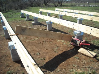
When it came time to attach the beams to the brackets, I had to bend the beams to an upright position as the beam, over the 40 foot length of it, was often torqued. I used a floor jack against a concrete pier and 2-by wood to do the work:

Using Floor Jack to Upright the Torqued Foundation Beams

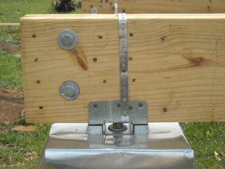
To keep the beams more securely fastened, it was suggested that I tie them to the concrete pier brackets with metal strapping:

Tying the Beams to the Concrete Pier Brackets Using Metal Strapping

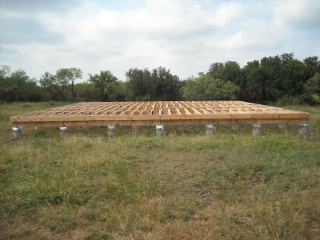
And here are the beams finished and in place! (I had originally thought I would need the entire end piers under the floor; but in looking back, given there is planned to be a porch, I probably would have moved the end piers all the way to the end of the beams.)

Built-up Beams in Place for Pier and Beam Foundation

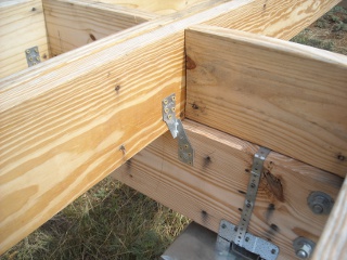
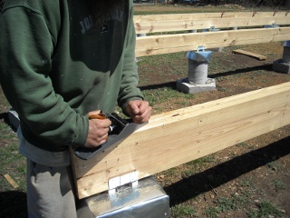
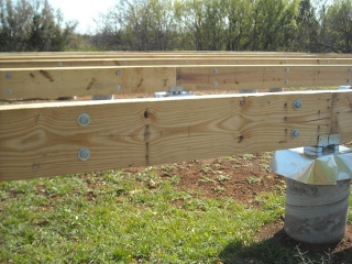
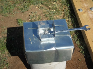
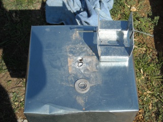
(Please see an update where I added some brackets to fortify the beam overhang, just as a precaution.)

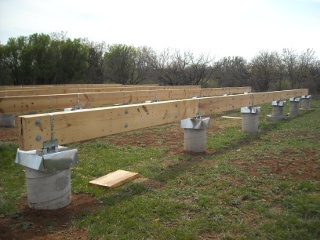
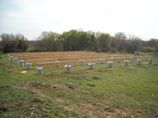
Here are a couple of wider angles:

General View of Built-up Beams in Place for Pier and Beam Foundation
Side View of Built-up Beams in Place for Pier and Beam Foundation

We once again thank the Lord for His gracious provision of the fellowship that He’s given us, and for the resources, strength, and guidance to continue with the building of the house.

— David
A House – Update V – Homemade Termite Shields

In studying on how to build a pier and beam foundation, and how to prevent against termites, I learned that there are termite shields available to put on top of a concrete pier. Well, I wasn’t able to obtain any locally; so I thought I might try to make them myself. The following is the process of how I did that:

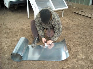
Since flashing is galvanized, which again helps against rust, I figured that would be a good material to use. I purchased 20″ flashing, and cut it into squares:

Cutting the Flashing for the Concrete Pier Homemade Termite Shield

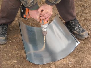
Since they had to fit over a 5/8″ bolt sticking out of the concrete pier, I drilled two 3/8″ holes next to each other in the center of the flashing squares; and I was able to drill three squares at a time easily:

Drilling the Center Hole for the Concrete Pier Homemade Termite Shield

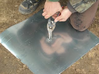
Since the two drilled holes were next to each other, and given the size of the pier’s bolt, I had to cut out the center hole a bit:

Cutting Out the Drilled Center Hole in the Flashing for the Concrete Pier Homemade Termite Shield

Here is the flashing pushed onto the pier. I usually had to work it down onto the bolt. Before putting it on, I sprinkled on some Seven termite powder because I heard that was a good thing to do, but my guess is the weather has removed most of it by now:

Flashing for the Concrete Pier Homemade Termite Shield Set in Place on the Pier

After placing the beam bracket on the shield over the bolt and finger tightening the nut down to hold the flashing in place, I folded the sides down to crease the flashing, and began to form it into its final shape. I originally tightened the bolt down all the way on quite a few of them, but realized that bent the brackets in the middle, which wouldn’t have allowed the beam to sit flat on them:

Folding the Sides of the Concrete Pier Homemade Termite Shield

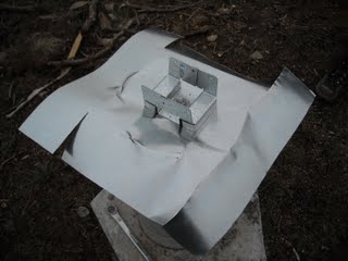
On opposite sides of the pier, and starting several inches in from the side edge of the flashing, I cut the folded flashing from the lower edge to a point where two perpendicular creases met in a line, creating a square out of two flashing edges and a cut edge; and I did this for all four corners:

Cut Sides of Concrete Pier Homemade Termite Shield

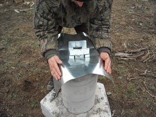
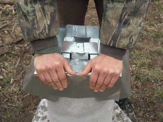
Then I positioned myself on one side where I had made the cuts, reached around the other side of the pier, and tucked in underneath the opposite side of the flashing the cut edges in each of my hands:

Folding the First Cut Sides of the Concrete Pier Homemade Termite Shield

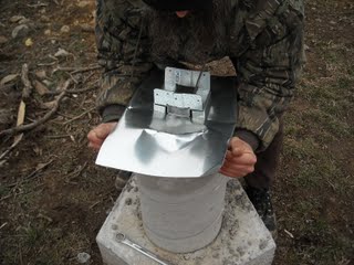
And then I folded the other sides on top of the tucked-in cut sides:

Folding the Final Cut Sides of the Concrete Pier Homemade Termite Shield

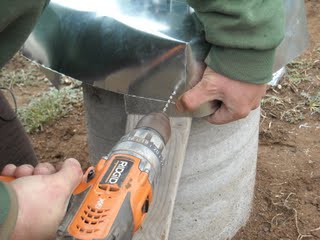
I didn’t want to leave the sides of the termite shield loose like that, so I decided to use rivets to fasten the corners in place. They are aluminum (again, to help against rust problems), and I chose 3/16″ short fastener rivets. I took a 2×4 and put it behind a folded corner to support the pressure of drilling; and using one hand, I closed the corner tightly around the 2×4. I then drilled a 3/16″ hole through the flashing in the corner of the overlapped flashing, and another hole in the corner of the folded-under flashing:

Drilling a Rivet Hole in the Concrete Pier Homemade Termite Shield

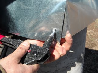
I then set the rivet in place…

Setting the Rivet in the Concrete Pier Homemade Termite Shield

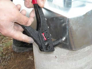
…and squeezed the rivet tool several times until the stem of the rivet cut off:

Using Rivet Tool on Concrete Pier Homemade Termite Shield

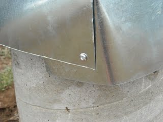
And here is the completed rivet:

Completed Rivet on Concrete Pier Homemade Termite Shield

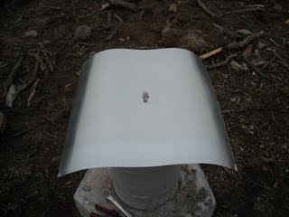
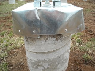
This is the completed termite shield:

Completed Concrete Pier Homemade Termite Shield

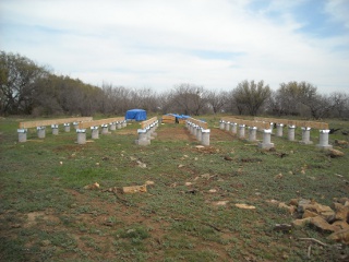
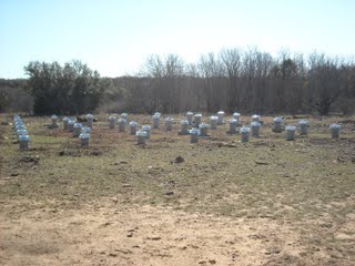
And here are all of the piers with all of their termite shields in place. No mind control for these concrete piers! 🙂

Concrete Piers with All Termite Shields Complete

We’re thankful to the Lord for His provisions, and for the idea and ability to put these together.

— David
 

« Older posts Newer posts »